CAUTION: The microprocessor and heat-sink assembly can get extremely hot. To avoid burns, be sure both have had sufficient time to cool before you touch them.
Disconnect the cooling fan power cable from the FAN connector on
the system board.
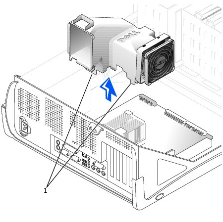
On the small mini-tower computer, remove the airflow shroud as
shown in the following illustration.
Airflow Shroud Removal—Small Mini-Tower Computer
1
Anchor tabs
Remove the cooling fan/heat-sink assembly.
Remove the memory module closest to the heat-sink assembly.
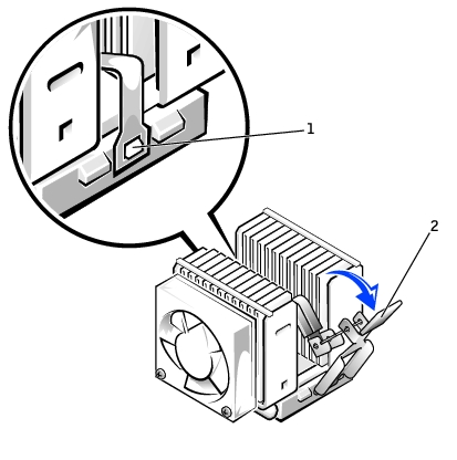
Pull down on the toggle clip lever until you can unhook the ends of
the clip from the tabs on each side of the ZIF socket.
Remove the clip from the socket, and then lift the heat sink from
the microprocessor.
Removing the Securing Clip
1
ZIF socket tab
2
Toggle lever
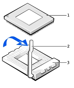
Remove the microprocessor chip from the socket.
Removing the Microprocessor Chip
1
Microprocessor chip
2
Release lever
3
Microprocessor socket
NOTICE: Be careful not to bend any of the pins when you remove the
microprocessor from the ZIF socket. Bending the pins can permanently
damage the microprocessor.
The ZIF socket has a lever-type handle that secures and releases the microprocessor from the ZIF socket.
Pull the socket release lever straight up until the microprocessor
releases.
Remove the microprocessor from the socket.
Leave the release lever extended so that the socket is ready for the new
microprocessor.
NOTICE: Be careful not to bend any of the pins when you unpack the
microprocessor. Bending the pins can permanently damage the microprocessor.
NOTICE: You must position the microprocessor correctly in the ZIF socket to
avoid permanent damage to the microprocessor and the computer when you
turn on the system.
Install the microprocessor in the ZIF socket.
If the release lever on the ZIF socket is not all the way out, move it to that position now.
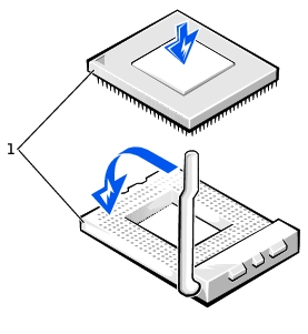
Align pin-1 (the corner marked with a triangle) of the microprocessor
and pin-1 of the ZIF socket.
Installing the Microprocessor Chip
1
Pin-1 corners of chip and socket aligned
Set the microprocessor lightly in the socket, making sure that all pins
are aligned with the correct holes.
Because the system uses a ZIF socket, there is no need to use force (which could bend the pins if the microprocessor is misaligned).
When the microprocessor is positioned correctly, press it with minimal
pressure to fully seat it in the ZIF socket.
When the microprocessor is fully seated, pivot the release lever back
toward the system board until it snaps into place, securing the
microprocessor.
NOTICE: Ground yourself by touching an unpainted metal surface on the
back of the computer.
Replace the fan/heat-sink assembly.
NOTICE: On the new heat sink, remove the plastic tab covering the thermal
grease before placing the assembly on the microprocessor.
Place the heat-sink assembly on top of the microprocessor.
Orient the metal retaining clip as shown in "Removing the
Securing Clip," and hook the unhinged end of the clip over the tab
on the top edge of the ZIF socket.
Rotate the lever upward until it snaps into place.
Replace the memory module that you removed in step 3 of the
previous procedure.
NOTE: If you are
installing a
microprocessor
replacement kit from Dell,
return the original heat-
sink assembly and
microprocessor to Dell in
the same package in
which your replacement
kit was sent. Your
microprocessor
replacement kit should
include a replacement
microprocessor heat sink.
You need to reuse the
original securing clip.
Reconnect the cooling fan power cable to the FAN connector on the
system board.
As the system boots, it detects the presence of the new microprocessor
and automatically changes the system configuration information in
system setup.
After you open and close the cover, the chassis intrusion detector
causes the following message to be displayed at the next system start-
up:
ALERT! Cover was previously removed.
Enter system setup and confirm that the system data area correctly
identifies the type of installed microprocessor.
For instructions on using system setup, see the User's Guide.
While in system setup, reset the Chassis Intrusion option by pressing
the left- or right-arrow key to select Reset and then choosing Enabled,
Enabled-Silent, or Disabled.
See the User's Guide for information on the chassis intrusion detector.
NOTE: If a setup
password has been
assigned by someone else,
contact the network
administrator for
information on resetting
the chassis intrusion
detector.
Run the Dell Diagnostics to verify that the new processor is operating
correctly.
See the User's Guide for information on Dell Diagnostics.