|
Overview | |
Adding Video Memory (OptiPlex GX1 Only) |
|
Expansion Cards | |
Upgrading the Microprocessor |
|
Adding Memory | |
Replacing the System Battery |
|
Overview | |
Adding Video Memory (OptiPlex GX1 Only) |
|
Expansion Cards | |
Upgrading the Microprocessor |
|
Adding Memory | |
Replacing the System Battery |
This chapter describes how to install the following options:
This chapter also includes instructions for replacing the system battery, if necessary.
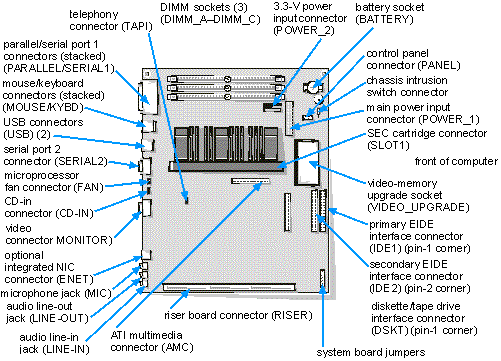
Use Figure 1 to locate the system board features.
Figure 1. System Board Features
|
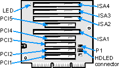
Expansion cards are installed on the computer's riser board (see Figure 3). The riser board plugs into the RISER connector on the system board (see Figure 1) and is considered an extension of the system board.
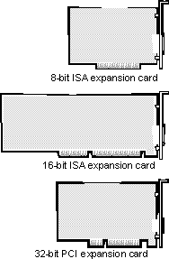
The system accommodates up to seven expansion cards, which can be a mix of 32-bit PCI expansion cards and 8- and 16-bit ISA expansion cards. (See Figure 2 for examples of ISA and PCI expansion cards.)
Figure 2. Expansion Cards
|
Nine expansion-card connectors reside on the riser board (see Figure 3). Because two expansion slots are shared, a maximum of seven expansion cards can be installed on the riser board.
 |
NOTE: On shared expansion slots, only one card of either type can be installed in the common slot. |
Figure 3. Riser-Board Expansion-Card Connectors
|
 |
CAUTION: To avoid the possibility of electric shock, turn off the computer and any peripherals, disconnect them from their electrical outlets, and then wait at least 5 seconds before you remove the computer cover. Also, before you install an expansion card, see "Safety First — For You and Your Computer." |
Follow this procedure to install an expansion card:
See "Using the ISA Configuration Utility" for instructions.
|
NOTE: If you install a PCI or Plug and Play expansion card, your system automatically performs any required configuration tasks during the boot routine. |
See the documentation that came with the expansion card for information on configuring the card, making internal connections, or otherwise customizing the card for your system.
|
CAUTION: Some network cards automatically start up the system when they are connected. To guard against electrical shock, be sure to unplug your computer from its electrical outlet before you install any expansion cards. |
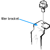
Save the screw to use when installing the expansion card later in this procedure.
Figure 4. Removing the Filler Bracket
|
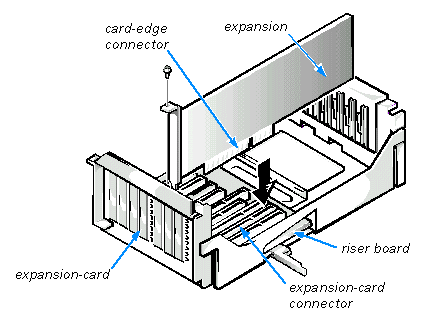
Insert the card-edge connector firmly into the expansion-card connector on the riser board. Gently rock the card into the connector until the card is fully seated (see Figure 5).
Figure 5. Installing an Expansion Card
|
See the documentation that came with the card for information about its cable connections.
|
NOTE: If Enabled, the Chassis Intrusion option will cause the following message to be displayed at the next system
start-up: ALERT! Cover was previously removed. |
|
CAUTION: To avoid the possibility of electric shock, turn off the computer and any peripherals, disconnect them from their electrical outlets, and then wait at least 5 seconds before you remove the computer cover. Also, before you install an expansion card, see "Safety First — For You and Your Computer." |
Follow this procedure to remove an expansion card:
See "Using the ISA Configuration Utility" for instructions.
|
NOTE: Installing filler brackets over empty card-slot openings is necessary to maintain Federal Communications Commission (FCC) certification of the system. The brackets also keep dust and dirt out of your computer. |
|
NOTE: If Enabled, the Chassis Intrusion option will cause the following message to be displayed at the next system start-up: ALERT! Cover was previously removed. |
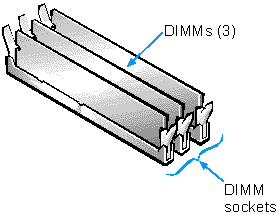
Memory can be increased to a maximum of 768 megabytes (MB) by installing combinations of 32-, 64-, 128-, or 256-MB dual in-line memory modules (DIMMs) in the three DIMM sockets on the system board. Figure 6 shows the DIMMs and DIMM sockets.
Your system can support both error checking and correction (ECC) and nonparity synchronous dynamic random-access memory (SDRAM) DIMMs. However, ECC support is available only if all DIMMs are ECC DIMMs. ECC DIMMs enable your system to correct all single-bit memory errors and detect multibit memory errors.
When you add system memory, you may install DIMMs in any socket. For optimum operation, Dell recommends that you install a DIMM in socket A first (closest to the processor) before installing a DIMM in another socket.
Figure 6. DIMMs and DIMM Sockets
|
Table 1 lists sample memory configurations and shows valid DIMM combinations and socket placements for each configuration.
Table 1. Sample DIMM Configuration Options
| Total Desired Memory |
DIMM Socket | ||
|---|---|---|---|
| A | B | C | |
| 32 MB | 32 MB | ||
| 64 MB | 64 MB | ||
| 64 MB | 32 MB | 32 MB | |
| 96 MB | 32 MB | 32 MB | 32 MB |
| 128 MB | 64 MB | 64 MB | |
| 128 MB | 128 MB | ||
| 160 MB | 128 MB | 32 MB | |
| 192 MB | 128 MB | 64 MB | |
| 192 MB | 128 MB | 32 MB | 32 MB |
| 256 MB | 128 MB | 128 MB | |
| 320 MB | 128 MB | 128 MB | 64 MB |
| 384 MB | 128 MB | 128 MB | 128 MB |
| 512 MB | 256 MB | 256 MB | |
| 768 MB | 256 MB | 256 MB | 256 MB |
|
CAUTION: To avoid the possibility of electric shock, turn off the computer and any peripherals, disconnect them from their electrical outlets, and then wait at least 5 seconds before you remove the computer cover. Also, before you install an expansion card, see "Safety First — For You and Your Computer." |
Follow this procedure to perform a memory upgrade:
Follow the instructions in "Installing a DIMM" or "Removing a DIMM," as appropriate.
|
NOTE: If Enabled, the Chassis Intrusion option will cause the following message to be displayed at the next system
start-up: ALERT! Cover was previously removed. |
The system detects that the new memory does not match the existing
system configuration information and generates the following message:
The amount of system memory has changed.
Strike the F1 key to continue, F2 to run the setup utility
The system should have already changed the value of System Memory to
reflect the newly installed memory modules. Verify the new total. If it is correct, skip
to step 9.
See your Diagnostics and Troubleshooting Guide for information on running the Dell Diagnostics and troubleshooting any problems that may occur.
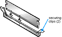
Use the following procedure to install a DIMM:
For optimum performance, DIMMs should be installed in consecutive sockets beginning with socket A.
Figure 7. Installing a DIMM
|
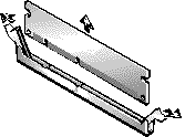
To remove a DIMM, press the securing clips outward (see Figure 8) simultaneously until the DIMM disengages from the socket (it should pop up slightly).
Figure 8. Removing a DIMM
|
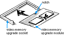
You can upgrade video memory on an OptiPlex GX1 from 4 to 8 MB by installing a video-memory upgrade module (OptiPlex GX1p systems come with 8 MB of video memory). Upgrading the video memory increases video performance and allows you to use video modes for application programs that require high resolutions and many colors.
|
CAUTION: To avoid the possibility of electric shock, turn off the computer and any peripherals, disconnect them from their electrical outlets, and then wait at least 5 seconds before you remove the computer cover. Also, before you install an expansion card, see "Safety First — For You and Your Computer." |
To upgrade the video memory, perform the following steps:
See Figure 1.
Figure 9. Installing a Video-Memory Upgrade Module
|
|
NOTE: If Enabled, the Chassis Intrusion option will cause the following message to be displayed at the next system
start-up: ALERT! Cover was previously removed. |
See your Diagnostics and Troubleshooting Guide for information on running the Dell Diagnostics and troubleshooting any problems that may occur.
To take advantage of future options in speed and functionality, you can replace the microprocessor on your system board with any Dell-supported microprocessor upgrade. Call your Dell sales representative for information on available microprocessor upgrades.
The microprocessor upgrade kit includes a new single-edge contact (SEC) cartridge with heat sink assembly and an airflow shroud.
|
CAUTION: Before you remove the computer cover, see "Safety First — For You and Your Computer." |
The following procedure describes how to replace the microprocessor.
|
NOTE: Dell recommends that only a technically knowledgeable person perform this procedure. |
|
CAUTION: The SEC cartridge and heat sink can get extremely hot during system operation. Be sure the assembly has had sufficient time to cool before you touch it. |
See Figure 1.
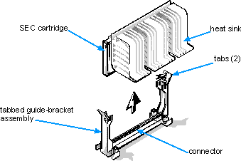
Squeeze the tabs on the top of the airflow shroud until the clips under the tabs disengage the top of the heat sink. Then lift the shroud from the cooling fan and SEC cartridge/heat sink assembly.
Press outward and hold the guide-bracket assembly latches, grasp the SEC cartridge/heat sink assembly firmly, and pull away from the connector on the system board. Lift the SEC cartridge/heat sink assembly from the guide bracket assembly.
|
NOTE: You must use up to 15 pounds of force to disengage the SEC cartridge from the connector. |
Figure 10. Removing the Microprocessor
|
Orient the SEC cartridge/heat sink assembly with the heat sink facing upward (as you face the front of the chassis). Align the sides of the heat sink with the guide brackets and press the SEC firmly into its connector until it is fully seated. The guide brackets will snap into place, securing the SEC cartridge in the connector on the system board.
|
NOTE: You must use up to 25 pounds of force to fully engage the SEC cartridge in the connector. |
Fit the mouth of the shroud in the alignment slots on the sides of the cooling fan. Then squeeze the tabs on the top of the shroud and lower it down until the clips under the tabs engage onto the top of the heat sink.
|
NOTE: If Enabled, the Chassis Intrusion option will cause the following message to be displayed at the next system
start-up: ALERT! Cover was previously removed. |
See your Diagnostics and Troubleshooting Guide for information on running the Dell Diagnostics and troubleshooting any problems that may occur.
A 3.0-volt (V) CR2032 coin-cell battery installed on the system board maintains system configuration, date, and time information in a special section of memory.
The operating life of the battery can extend up to ten years. The battery may need replacing if an incorrect time or date is displayed during the boot routine along with a message such as:
Time-of-day not set - please run SETUP program
or
Invalid configuration information - please run SETUP program
or
Strike the F1 key to continue, F2 to run the setup utility
To determine whether the battery needs replacing, reenter the time and date through the System Setup program (not through the MS-DOS time and date commands) and exit the program properly to save the information (see "Using the System Setup Program" for instructions). Turn off your system and disconnect it from AC power for a few hours; then reconnect and turn on your system. Enter the System Setup program. If the date and time are not correct in the System Setup program, replace your battery.
You can operate your system without a battery; however, without a battery, the system configuration information is erased if the system is turned off or unplugged from AC power. In this case, you must enter the System Setup program and reset the configuration options.
|
CAUTION: There is a danger of the new battery exploding if it is incorrectly installed. Replace the battery only with the same or equivalent type recommended by the manufacturer. Discard used batteries according to the manufacturer's instructions. |
|
CAUTION: Before you remove the computer cover, see "Safety First — For You and Your Computer." |
Use the following procedure to replace the system battery with another CR2032 coin-cell battery:
If the settings are lost while you are replacing the battery, refer to your written or printed copy of the system configuration information to restore the correct settings. See "
Using the System Setup Program" for instructions.| NOTICE: If you pry the battery out of its socket with a blunt object, be careful not to touch the system board with the object. Make certain that the object is inserted between the battery and the socket before attempting to pry out the battery. Otherwise, you may damage the system board by prying off the socket or by breaking circuit traces on the system board. |
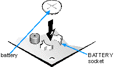
The battery (see Figure 1) is mounted in a socket labeled "BATTERY" in the front-right corner of the system board (as you face the front of the system).
Pry the battery out of its socket with your fingers or with a blunt, nonconductive object, such as a plastic screwdriver.
Orient the battery with the side labeled "+" facing up (see Figure 11). Then insert the battery into the socket, and snap it into place.
Figure 11. System Battery and Battery Socket
|
|
NOTE: If Enabled, the Chassis Intrusion option will cause the following message to be displayed at the next system start-up: ALERT! Cover was previously removed. |